chapt 9-86-82
DownloadTélécharger
Actions
Vote :
ScreenshotAperçu
Informations
Catégorie :Category: mViewer GX Creator Lua TI-Nspire
Auteur Author: did
Type : Classeur 3.6
Page(s) : 11
Taille Size: 736.41 Ko KB
Mis en ligne Uploaded: 03/05/2015 - 19:00:19
Uploadeur Uploader: carl cox (Profil)
Téléchargements Downloads: 268
Visibilité Visibility: Archive publique
Shortlink : https://tipla.net/a208340
Type : Classeur 3.6
Page(s) : 11
Taille Size: 736.41 Ko KB
Mis en ligne Uploaded: 03/05/2015 - 19:00:19
Uploadeur Uploader: carl cox (Profil)
Téléchargements Downloads: 268
Visibilité Visibility: Archive publique
Shortlink : https://tipla.net/a208340
Description
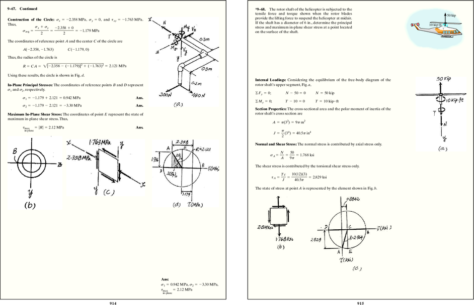
9–67. Continued *9–68. The rotor shaft of the helicopter is subjected to the
tensile force and torque shown when the rotor blades 50 kip
Construction of the Circle: sx = - 2.358 MPa, sy = 0, and txy = - 1.763 MPa . provide the lifting force to suspend the helicopter at midair.
Thus, If the shaft has a diameter of 6 in., determine the principal 10 kip!ft
sx + sy -2.358 + 0 stress and maximum in-plane shear stress at a point located
savg = = = - 1.179 MPa on the surface of the shaft.
2 2
The coordinates of reference point A and the center C of the circle are
A(-2.358, - 1.763) C(- 1.179, 0)
Thus, the radius of the circle is
R = CA = 2[ - 2.358 - ( -1.179)]2 + (- 1.763)2 = 2.121 MPa
Using these results, the circle is shown in Fig. d.
Internal Loadings: Considering the equilibrium of the free-body diagram of the
In-Plane Principal Stresses: The coordinates of reference points B and D represent rotor shaft’s upper segment, Fig. a,
s1 and s2, respectively.
©Fy = 0; N - 50 = 0 N = 50 kip
s1 = - 1.179 + 2.121 = 0.942 MPa Ans.
©My = 0; T - 10 = 0 T = 10 kip # ft
s2 = - 1.179 - 2.121 = - 3.30 MPa Ans.
Section Properties: The cross-sectional area and the polar moment of inertia of the
Maximum In-Plane Shear Stress: The coordinates of point E represent the state of rotor shaft’s cross section are
maximum in-plane shear stress. Thus,
A = p(32) = 9p m2
tmax = |R| = 2.12 MPa Ans.
in-plane p 4
J = (3 ) = 40.5p in4
2
Normal and Shear Stress: The normal stress is contributed by axial stress only.
N 50
sA = = = 1.768 ksi
A 9p
The shear stress is contributed by the torsional shear stress only.
Tc 10(12)(3)
tA = = = 2.829 ksi
J 40.5p
The state of stress at point A is represented by the element shown in Fig. b.
Ans:
s1 = 0.942 MPa, s2 = - 3.30 MPa,
tmax = 2.12 MPa
in-plane
914 9 15
9–68. Continued *9–69. The pedal crank for a bicycle has the cross section
shown. If it is fixed to the gear at B and does not rotate
Construction of the Circle: sx = 0, sy = 1.768 ksi, and txy = 2.829 ksi. Thus, while subjected to a force of 75 lb, determine the principal 75 lb
stress in the material on the cross section at point C.
sx + sy 0 + 1.768
savg = = = 0.8842 ksi B A
2 2 3 in. 4 in.
C
The coordinates of reference point A and the center C of the circle are 0.4 in.
0.4 in.
A(0, 2.829) C(0.8842, 0) 0.2 in.
0.3 in.
Thus, the radius of the circle is
Internal Forces and Moment: As shown on FBD
R = CA = 2(0 - 0.8842)2 + 2.8292 = 2.964 ksi
Section Properties:
Using these results, the circle is shown in Fig. c.
(0.3) A 0.83 B = 0.0128 in3
1
In-Plane Principal Stress: The coordinates of reference points B and D represent s1 I =
and s2, respectively. 12
s1 = 0.8842 + 2.964 = 3.85 ksi Ans. QC = y¿A¿ = 0.3(0.2)(0.3) = 0.0180 in3
s2 = 0.8842 - 2.964 = - 2.08 ksi Ans. Normal Stress: Applying the flexure formula.
Maximum In-Plane Shear Stress: The state of maximum shear stress is represented My -300(0.2)
by the coordinates of point E, Fig. a. sC = - = - = 4687.5 psi = 4.6875 ksi
I 0.0128
tmax = R = 2.96 ksi Ans.
in-plane Shear Stress: Applying the shear formula.
VQC 75.0(0.0180)
tC = = = 351.6 psi = 0.3516 ksi
It 0.0128(0.3)
Construction of the Circle: In accordance with the sign convention, sx = 4.6875 ksi,
sy = 0, and txy = 0.3516 ksi. Hence,
sx + sy 4.6875 + 0
savg = = = 2.34375 ksi
2 2
The coordinates for reference points A and C are
A(4.6875, 0.3516) C(2.34375, 0)
The radius of the circle is
R = 2(4.6875 - 2.34375)2 + 0.35162 = 2.370 ksi
In-Plane Principal Stress: The coordinates of point B and D represent s1 and s2,
respectively.
s1 = 2.34375 + 2.370 = 4.71 ksi Ans.
s2 = 2.34375 - 2.370 = - 0.0262 ksi Ans.
Ans:
s1 = 4.71 ksi, s2 = - 0.0262 ksi
916 91 7
9–70. A spherical pressure vessel has an inner radius of 9–71. The cylindrical pressure vessel has an inner radius
5 ft and a wall thickness of 0.5 in. Draw Mohr’s circle for 458 458
of 1.25 m and a wall thickness of 15 mm. It is made from
the state of stress at a point on the vessel and explain the 1.25 m steel plates that are welded along the 45° seam. Determine 1.25 m
significance of the result. The vessel is subjected to an the normal and shear stress components along this seam if
internal pressure of 80 psi. the vessel is subjected to an internal pressure of 8 MPa.
Normal Stress: pr 8(1.25)
sx = = = 333.33 MPa
pr 80(5)(12) 2t 2(0.015)
s1 = s2 = = = 4.80 ksi
2t 2(0.5) sy = 2sx = 666.67 MPa
Mohr’s circle: A(333.33, 0) B(666.67, 0) C(500, 0)
A(4.80, 0) B(4.80, 0) C(4.80, 0) 333.33 + 666.67
sx¿ = = 500 MPa Ans.
2
Regardless of the orientation of the element, the shear stress is zero and the state of
stress is represented by the same two normal stress components. Ans. tx¿y¿ = -R = 500 - 666.67 = - 167 MPa Ans.
Ans:
Regardless of the orientation of the element,
the shear stress is zero and the state of stress is
represented by the same two normal stress Ans:
components. sx¿ = 500 MPa, tx¿y¿ = - 167 MPa
918 9 19
*9–72. Determine the normal and shear stresses at point D 10 kN 9–72. Continued
that act perpendicular and parallel, respectively, to the grains.
The grains at this point make an angle of 30° with the Then
horizontal as shown. Point D is located just to the left of the
10-kN force. D B sx¿ = 0.5556 - 0.5984 cos 81.80° = 0.4702 MPa = 470 kPa Ans.
A 100 mm 308
1m 1m tx¿y¿ = 0.5984 sin 81.80° = 0.5922 MPa = 592 kPa Ans.
2m
D 300 mm C
100 mm
100 mm
Using the method of section and consider the FBD of the left cut segment, Fig. a
+ c ©Fy = 0; 5 - V = 0 V = 5 kN
a + ©MC = 0; M - 5(1) = 0 M = 5 kN # m
The moment of inertia of the rectangular cross - section about the neutral axis is
1
I = (0.1)(0.33) = 0.225(10 - 3) m4
12
Referring to Fig. b,
QD = y¿A¿ = 0.1(0.1)(0.1) = 0.001 m3
The normal stress developed is contributed by bending stress only. For point D,
y = 0.05 m. Then
My 5(103)(0.05)
s = = = 1.111 MPa (T)
I 0.225(10 - 3)
The shear stress is contributed by the transverse shear stress only. Thus,
VQD 5(103)(0.001)
t = = = 0.2222 MPa
It 0.225(10 - 3)(0.1)
The state of stress at point D can be represented by the element shown in Fig. c
In accordance with the established sign convention, sx = 1.111 MPa, sy = 0 and
txy = - 0.2222 MPa, Thus.
sx + sy 1.111 + 0
savg = = = 0.5556 MPa
2 2
Then, the coordinate of reference point A and the center C of the circle are
A(1.111, - 0.2222) C(0.5556, 0)
Thus, the radius of the circle is given by
R = 2(1.111 - 0.5556)2 + ( -0.2222)2 = 0.5984 MPa
Using these results, the circle shown in Fig. d can be constructed.
Referring to the geometry of the circle, Fig. d,
a = tan - 1 a b = 21.80°
0.2222
b = 180° - (120° - 21.80°) = 81.80°
1.111 - 0.5556
920 9 21
9–73. Determine the principal stress at point D, which is 10 kN 9–73. Continued
located just to the left of the 10-kN force.


, reçois gratuitement 1 exemplaire de test de la TI-82 Advanced Edition Python. À demander d'ici le 31 décembre 2024.")