chap 5 77-89
DownloadTélécharger
Actions
Vote :
ScreenshotAperçu
Informations
Catégorie :Category: mViewer GX Creator Lua TI-Nspire
Auteur Author: didi
Type : Classeur 3.6
Page(s) : 7
Taille Size: 449.58 Ko KB
Mis en ligne Uploaded: 03/05/2015 - 18:51:23
Uploadeur Uploader: carl cox (Profil)
Téléchargements Downloads: 596
Visibilité Visibility: Archive publique
Shortlink : https://tipla.net/a208327
Type : Classeur 3.6
Page(s) : 7
Taille Size: 449.58 Ko KB
Mis en ligne Uploaded: 03/05/2015 - 18:51:23
Uploadeur Uploader: carl cox (Profil)
Téléchargements Downloads: 596
Visibilité Visibility: Archive publique
Shortlink : https://tipla.net/a208327
Description
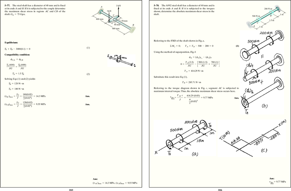
5–77. The steel shaft has a diameter of 40 mm and is fixed A 3 kN 5–78. The A992 steel shaft has a diameter of 60 mm and is
at its ends A and B. If it is subjected to the couple determine fixed at its ends A and B. If it is subjected to the torques 200 N!m
the maximum shear stress in regions AC and CB of the 3 kN shown, determine the absolute maximum shear stress in the B
shaft. Gst = 75 Gpa . C shaft. 1m
500 N!m D
400 mm
50 mm 1.5 m
C
50 mm B
A 1m
600 mm
Referring to the FBD of the shaft shown in Fig. a,
Equilibrium:
©Mx = 0; TA + TB - 500 - 200 = 0 (1)
TA + TB - 3000(0.1) = 0 (1)
Using the method of superposition, Fig. b
Compatibility condition:
fA = (fA)TA - (fA)T
fC>A = fC>B
TA (3.5) 500 (1.5) 700 (1)
TA (400) TB (600) 0 = - c + d
= JG JG JG
JG JG
TA = 414.29 N # m
TA = 1.5 TB (2)
Substitute this result into Eq (1),
Solving Eqs (1) and (2) yields:
TB = 285.71 N # m
TB = 120 N # m
TA = 180 N # m Referring to the torque diagram shown in Fig. c, segment AC is subjected to
maximum internal torque. Thus, the absolute maximum shear stress occurs here.
Tc 180(0.02) TAC c
(tAC)max = = p = 14.3 MPa Ans. 414.29 (0.03)
4 tabs = = = 9.77 MPa
2 (0.02 )
J max Ans.
J p
120(0.02) (0.03)4
Tc 2
(tCB)max = = p 4
= 9.55 MPa Ans.
2 (0.02 )
J
Ans: Ans:
(tAC)max = 14.3 MPa, (tCB)max = 9.55 MPa tabs = 9.77 MPa
max
385 38 6
5–79. The steel shaft is made from two segments: AC has A *5–80. The shaft is made of A-36 steel and is fixed at its
0.5 in.
a diameter of 0.5 in., and CB has a diameter of 1 in. If the ends A and D. Determine the torsional reactions at these 1.5 ft
shaft is fixed at its ends A and B and subjected to a torque C supports.
of 500 lb # ft, determine the maximum shear stress in the 5 in. D 500 lb!ft 2 ft
shaft. Gst = 10.8(103) ksi .
8 in. 1 in. A
1.5 ft
B B
12 in. 40 kip!ft
C
20 kip!ft
Equilibrium: 6 in. D
Equilibrium: Referring to the free-body diagram of the shaft shown in Fig. a,
TA + TB - 500 = 0 (1)
©Mx = 0; TA + TD + 20 - 40 = 0 (1)
Compatibility condition: Compatibility Equation: Using the method of superposition, Fig. b,
fD>A = fD>B
fA = (fA)T - (fA)TA
TA(5) TA(8) TB(12) 40(12)(2)(12) 20(12)(1.5)(12) TA(12)(5)(12)
p 4
+ p 4
= p 4 0 = c + d -
2 (0.25 )G 2 (0.5 )G 2 (0.5 )G JG JG JG
1408 TA = 192 TB (2)
TA = 22 kip # ft Ans.
Solving Eqs. (1) and (2) yields
Substituting this result into Eq. (1),
TA = 60 lb # ft TB = 440 lb # ft
TD = - 2 kip # ft = 2 kip # ft Ans.
Tc 60(12)(0.25)
tAC = = p 4
= 29.3 ksi (max) Ans. The negative sign indicates that TD acts in the sense opposite to that shown on the
2 (0.25 )
J
free-body diagram.
Tc 440(12)(0.5)
tDB = = p 4
= 26.9 ksi
2 (0.5 )
J
Ans:
tmax = 29.3 ksi
387 38 8
5–81. The shaft is made of A-36 steel and is fixed at end D, 5–82. The shaft is made from a solid steel section AB and
while end A is allowed to rotate 0.005 rad when the torque 1.5 ft a tubular portion made of steel and having a brass core.
If it is fixed to a rigid support at A, and a torque of 3 ft
is applied. Determine the torsional reactions at these
supports. 2 ft T = 50 lb # ft is applied to it at C, determine the angle of
twist that occurs at C and compute the maximum shear
A 2 ft
stress and maximum shear strain in the brass and steel.
Take Gst = 11.511032 ksi, Gbr = 5.611032 ksi.
1.5 ft A
B
40 kip!ft
0.5 in.
C B
20 kip!ft
D 1 in. T " 50 lb!ft
6 in. Equilibrium: C
Equilibrium: Referring to the free-body diagram of the shaft shown in Fig. a, Tbr + Tst - 50 = 0 (1)
©Mx = 0; TA + TD + 20 - 40 = 0 (1) Both the steel tube and brass core undergo the same angle of twist fC>B
Compatibility Equation: Using the method of superposition, Fig. b, TL Tbr (2)(12) Tst (2)(12)
fC>B = = =
JG p
2 (0.54)(5.6)(106) p
2 (14 - 0.54)(11.5)(106)
fA = (fA)T - (fA)TA
Tbr = 0.032464 Tst (2)
40(12)(2)(12) 20(12)(1.5)(12) TA(12)(5)(12)
0.005 = + - Solving Eqs. (1) and (2) yields:
J p (34)(11.0)(103) p (34)(11.0)(103) K p 4
(3 )(11.0)(103)
2 2 2 Tst = 48.428 lb # ft; Tbr = 1.572 lb # ft
TA = 12.28 kip # ft = 12.3 kip # ft Ans. TL 1.572(12)(2)(12) 50(12)(3)(12)
fC = © = p 4 6
+ p 4 6
JG 2 (0.5 )(5.6)(10 ) 2 (1 )(11.5)(10 )
Substituting this result into Eq. (1),
TD = 7.719 kip # ft = 7.72 kip # ft Ans. = 0.002019 rad = 0.116° Ans.
TABc 50(12)(1)
(tst)max AB = = p 4
= 382 psi
J 2 (1 )
Tst c 48.428(12)(1)


, reçois gratuitement 1 exemplaire de test de la TI-82 Advanced Edition Python. À demander d'ici le 31 décembre 2024.")